Inspection and Testing Series. Part 2 - Continuity
10 October 2019
Welcome back to Training In Electricals Inspection and Testing
blog series.
In part 2 we will now be completing the continuity stages.
Continuity is the continuous path of the cable that should be unbroken. Continuity is to be proven before the installation is brought into service as well proving their integrity during a periodic inspection. This is done as a dead test, see part 1 for the correct safe isolation procedure which is required to be completed prior to starting your continuity tests.
Using your low resistance ohms meter, you will complete the following 3 or 4 continuity tests across the system.
Continuity of Bonding - Guidance Note 3 (Page 41)
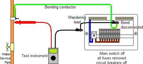
Disconnect the main protective bonding conductor (10 mm cable) at the MET to remove any possible parallel paths. Test the conductor resistance from one end to the other including any clamps that may be used, by testing onto the pipework, containment, building framework. As per the Guidance Note 3 the reading expected should not exceed 0.07 Ohms
Continuity of Radial Circuits and Polarity - Guidance Note 3 (Page 45, Page 59)
Place a temporary link between the Line (R1) and the CPC (R2) at the Distribution Board. The temporary link can be a short length of cable or a jump lead with crocodile clips on each end. This is also referred as R1+R2 method. At every point in the circuit, test between Line (R2 and CPC (R2). Ensure two-way switching arrangements are operated during the test at lighting points to ensure all line conductors are continuous and the circuit works as desired. By operating any switch on the circuit during the test and observing the readings, open and close can also confirm Polarity of the circuit.
The highest reading taken during the test is entered onto the schedule of test results in the R1+R2 column (Column 15). If polarity was verified, the polarity column can be ticked (Column 20)
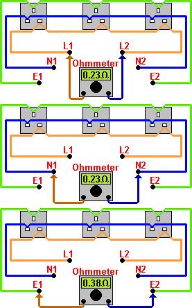
Continuity of ring final circuits - Guidance Note 3 (Page 45)
The test is undertaken in Three Steps and you must follow all the steps in the correct sequence.
Step 1 – Test end to end resistance of the ring at the distribution board between the disconnected conductors and note down the reading as:
Line to line: r1 (Column 12)
Neutral to neutral: rn (Column 13)
CPC to CPC: r2 (Column 14)
The readings taken should be the same if all conductors have the same CSA and are correctly wired. If the R2 has a reduced CSA, the reading r2 will be proportionally higher.
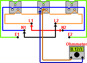
Step 2 – Interconnect, using a connector or jump lead, the Line (r1) of one leg of the ring to the neutral (rn)of the other leg, then the remaining line and neutral together. This forms a figure 8 configuration. It is referred to as figure 8 owing to the way conductors are configured during the test. At every socket outlet on the circuit, test between Line and Neutral, the reading should be consistently similar at every socket outlet, providing they are connected into the ring and not spurs. The results obtained at each socket outlet should be very close to the results calculated as (r1+rn)/4. These results are not recorded anywhere but the test should be completed to identify any spurs in the ring circuit.
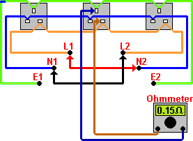
Step 3 – Interconnect, using a connector, lines and circuit protective conductors to for the figure of 8. At every socket outlet on the circuit, test between Line and CPC. The reading should be consistently similar at every socket outlet, providing they are connected into the ring and not spurs. The results obtained at each socket outlet should be very close to the results calculated as (r1+r2)/4. These are recorded in (Column 15) If any result is higher than expected, once all the results are gathered, check to see if the socket outlet where higher results were obtained is wired as a spur.
You have now sucessfully completed your Continuity Tests. Part 3 Will follow on with insulation resistance testing. To Learn more about our Inspection and Testing courses see please call us on 0115 8228 645.
Share this article